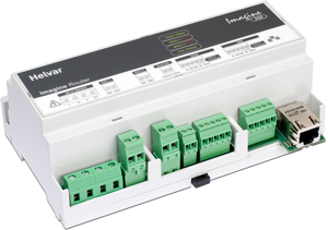
920 – Imagine Router

 |
920 – Imagine Router |
 |
|

The 920 Imagine Router is a building block for architectural, ‘architainment’ and commercial lighting control systems. It allows seamless integration of DIGIDIM and Imagine systems.
The 905, 910 and 920 Routers can be freely mixed within the same system.
The 920 Router features:
Ethernet connector
Two DALI subnet connectors
SDIM subnet connector for 252 channels
DMX subnet connector for 512 DMX channels.
Override output connector
Mains supply (AC) |
|
L |
(Live) |
N |
(Neutral) |
E |
(Earth / Ground): must be connected |
SC |
(Screen connection) |
DALI 1 & DALI 2 |
|
DA- |
|
DA+ |
|
Override |
|
Source |
|
Sink |
|
SDIM |
|
A: |
(Data + ) |
B: |
(Data -) |
0 V |
(Data reference) |
SC |
(Screen: not data reference) |
Term |
(Link to B for termination) |
DMX |
|
A: |
(Data + ) |
B: |
(Data -) |
0 V |
(Data reference) |
SC |
(Screen: not data reference) |
Term |
(Link to B for termination) |
Ethernet (To hub, switch or PC) |
|
There are 4 LEDs for:
Power / Status. LED is on (green) when the router is powered on (blinks slowly for normal operation / blinks rapidly if there is a problem).
DALI 1 / SDIM. LED is on (green) for DALI power and blinks for DALI activity / blinks (red) for SDIM activity. If there is a DALI line fault, LED switches off and stays off.
DALI 2 / DMX. LED is on (green) for DALI power and blinks for DALI activity / blinks (red) for DMX activity. If there is a DALI line fault, LED switches off and stays off.
Link / Activity. LED is on (green) when router is connected to Ethernet and blinks for activity.
For further information regarding LED status, flash codes and error identification, see:
Upgrade Router Firmware
905/910/920 LED Flash Codes After Detection of an Error State