DALI Control Gear Configuration

 |
DALI Control Gear Configuration |
 |
|
Note:
|
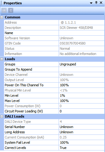
Click on the DALI control gear item in the Devices View.
If the Properties View for the item is not already open, select View > Properties, or press F4.

It is useful to name the item e.g. according to its location or purpose:
In the Common section, click in the Name field.
Enter a name for the device.
Click ![]() . The device is renamed in the Devices view.
. The device is renamed in the Devices view.
Click in Groups field.
Enter the group to be assigned to the item. If you want to assign more than one group, insert a comma after each Group number, e.g. 1, 3, 7 (or enter more groups in the Groups To Append field, see below).
Click ![]() .
.
In the Loads section, click in Groups To Append field.
Enter the group to be assigned to the item. This will maintain the current grouping. If you want to assign more than one group, insert a comma after each Group number, e.g. 1, 3, 7
Click ![]() .
.
This is the level/scene to which the channelwill go when the router and/or control gear is powered on.
You can set this channel to power on to a specific scene, level, last level before fail, off, or the minimum, maximum or system fail levels.
Notes:
|
Click in the Power On This Channel To field.
Click ![]() and select a lighting setting for the channel to power on to.
and select a lighting setting for the channel to power on to.
Click ![]() .
.
This is the minimum level that the channel will achieve, no matter what scene is called or level is set. For example, if you set a minimum level of 50 % and call scene 4 (at 25 % level), the channel output level will be 50 %.
Click in the Min Level field.
Enter a percentage value (1 % – 100 %).
Click ![]() .
.
This is the maximum level that the channel will achieve, no matter what scene is called or level is set. For example, if you set a maximum level of 50 % and call scene 2 (at 75 % level), the channel output level will be 50 %.
Click in the Max Level field.
Enter a percentage value (1 % – 100 %).
Click ![]() .
.
Note:
|
DIGIDIM/DALI control gear does not measure its own power consumption. Calculate the total power consumption of all the lamps connected to the load and enter this amount in this field (this will be an estimation of the total power consumption of the device).
Click in the Circuit Power Loading field.
Enter a value in the range from 0 to 16 384 W (0.25 W resolution).
Click ![]() .
.
Note:
|
Enter the short address of the emergency ballast to be used in case of ballast failure.
Click in the Emergency Ballast Address field.
Enter the short address of the emergency ballast, connected to the same tube.
Click ![]() .
.
The channel is set to this level in the event of a DALI power supply failure.
Click in the System Fail Level field.
Enter a percentage value (1 % – 100 %) or click ![]() and select 'Ignore'.
and select 'Ignore'.
Click ![]() .
.
Note:
|
To configure the Output Mode field:
In the Properties view, click in the Output Mode field.
Click ![]() and select the mode of operation for the output.
and select the mode of operation for the output.
Notes:
|
Select this mode for a 0 V or 10 V analogue output signal. The 10 V signal is through a 'pull-up' resistor. The output used with this mode is either ON or OFF (switched).
Select this mode for a 1–10 V analogue output signal. The 10 V signal is through a 'pull-up' resistor. This mode can be used for controlling ballasts, for example.
Select this mode for a 0–10 V analogue output signal.
This mode generates high pulse signals from low values (low levels). It allows a full range of values (0 % – 100 %). It generates a low level signal for 0 % level and adjusts (pulse width modulates) high pulses up to 100 %.
This mode generates low pulse signals from high values (high levels). It allows a full range of values (1 % – 100 %). It generates a high level signal for 0 % level and adjusts (pulse width modulates) low pulses up to 100 %.
Select this mode so that the output communicates with all DALI (DIGIDIM) loads.
This mode is used for Tridonic ballasts, ballasts that accept the DSI protocol, and also control devices which communicate to DSI ballasts using the DSI protocol.
Note:
|
Click ![]()
Notes:
|
The device is now configured and ready for use in the lighting system.