Working with Open Loop Constant Light |
|||
Open Loop Constant Light control is a method of automating the operation of the system’s lamps. Its use can provide a great deal of convenience for the building’s occupants, but perhaps the main reason for using it is that it can provide a considerable increase in energy efficiency. It ensures that the output of the lamps is no higher than is required to maintain the desired light level.
For buildings fitted with air conditioning systems, there is an additional saving associated with reducing the need to remove waste heat.
|
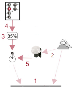
The effect of this is that the lamps should only output sufficient light to maintain the desired level of light in the room. This means that the lamps can be operating at minimum when the room is filled with sunlight. The lamp’s output will gradually increase as night falls, or the sky becomes overcast. Since the lamps will only provide the amount of light that is necessary, they will use the absolute minimum amount of energy, in order to achieve the desired light level. |
The art of designing a successful Open Loop Constant Light control system is to position the external sensor carefully, profile the controlled areas to understand daylight contribution under various sky conditions and to suitably match the Source Level for Direct Proportion levels.
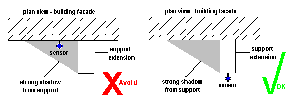
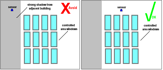
It is essential that the light sensor measurement accurately represents the lighting conditions if predictable and consistent results are to be achieved and for this there are two critical effects that ideally should be avoided, shadowing and hot-spotting.
In the ideal a building would be isolated and removed from other structures with a sensor mounted on the roof and away from obstructions.
In practice there will be adjacent buildings and obstructions that can give strong shadows at various times of the day and during the course of the year. One solution is for the sensor to be mounted in association with the controlled area and thereby minimise compromise. In all cases careful thought to sensor siting will save programming and response compromises.
Where a single sensor is to be used with multiple controlled areas or if simply there are practical restrictions to mounting location and height then compromises will be inevitable and these must be understood and accommodated. Typically the control system could be programd to ignore light changes at certain times of the day or month, etc.
When complex shadowing cannot be avoided it can be beneficial to locate the sensor in permanent shadow such that it measures the skylight only. This will give a consistent measurement but will not reflect the local effects of strong sunlight interspersed with shadow. Here more careful consideration is required to The Source Level for Direct Proportion table values.
Hot-spotting is a consequence of an unwanted reflection giving additional light to the sensor. Predicting a problem can be difficult as for example the effect of opening a nearby window can easily be missed.
There are important practical factors to be aware of:
The external sensor functions on an open loop principle, and has no means of knowing either the capabilities of the lamps or the effect of modifying their output. This means that it is possible to set the source level correctly for one type of light whilst being totally inappropriate for another. Correct profiling, that is understanding the effect of modifying the artificial light level for the controlled area with respect to the contributing daylight is essential in achieving the intended operation.
If there are methods of controlling the daylight locally, such as blinds, then this must be factored into the design strategy. For example, if the blinds are controlled as part of the lighting control system then conditions can be applied to the Open Loop Constant Light routing entry to effect a change in response.
The light level measured by the external light sensor is the LUX value at its location and can not be calibrated to correspond to a specific LUX level produced by the lighting system.
Attaining specific LUX levels for your installation requires accurate profiling to determine the appropriate Direct Proportion reduction in the artificial lighting in response to available daylight. The contributing daylight of the controlled area relative to the external LUX level and thereby the supplementary lighting, if any, required from the artificial lighting needs to be measured and the results used to create the Source Level for Proportion Control profile table.
One method you can obtain an approximate setting is as follows:
1. Place a LUX meter in the working plane to be controlled.
2. Adjust the lamps until the LUX meter shows the desired value.
3. Record the Current Light Level reported by the external sensor.
4. Compare the % light against the default Direct Proportion for the daylight and intended starting constant light scene.
5. Modify, if necessary, the Source Level for the Direct Proportion needed then scale other source levels accordingly.
Note:
|
Open Loop Constant Light operation may require the use of two groups. The first of these, known as the Input Group (Light Sensor), contains the controllers that are to be used to set up and control open loop constant light operation. The second, the Output Group (Controlled Loads), contains the LIUs (Lamp Interface Units, or loads) for the lamps that are to be subject to open loop constant light control.
Tip:
|
The same external light sensor (Input Group) can be used to control as many output groups as desired each simply requiring a separate routing entry.
A useful feature for numerous areas serviced by the same windows is to group the lighting in sections corresponding to the distance from the windows. This allows scaling from the window group(s) to the more distant groups but with the same Source Level profile.
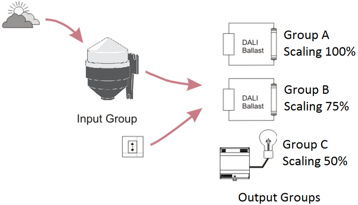
Recall of an Open Loop Constant Light scene in the Input Group results in that scene being called in the Output Group, and the Scaling of the Source Level for Direct Proportion being applied. After a settling period, the lights in the Output Group are automatically adjusted.